This post originated from an RSS feed registered with Python Buzz
by Aaron Brady.
Original Post: Radio
Feed Title: insom.me.uk
Feed URL: http://feeds2.feedburner.com/insommeuk
Feed Description: Posts related to using Python. Some tricks and tips, observations, hacks, and the Brand New Things.
A little over a month ago, I posted on my Tumblr about building a cheap
Arduino clone (which is stretching the term to mean running the Arduino
bootloader on a bare ATmega) for some radio experiments.
Hello World
I got “Hello, World” working (or, I got “68656c6c6f” working, really) with full-size
Arduino and Boarduino boards. The VirtualWire library makes this really
simple (though the library is now deprecated in favour of RadioHead).
We even had a little fun in the office hooking up
a DHT11 temperature sensor and a batch of LEDs repurposed as ‘light level detectors’
and feeding those into the big graphing stack we use.
Jealousy
This tied up a FTDI RS232 cable and was highly inelegant. I saw Dickson Chow’s
Plant Friends and was instantly jealous. I wanted to make something as tidy
as that.
Using a Raspberry Pi to receive the VirtualWire protocol is
difficult - the Arduino only has one thing to do and you can easily register
your own interrupt handler (which is what VirtualWire does) - so timing sensitive
protocols aren’t (much of) a problem. These exact things are a problem
when you’re running a multi-tasking operating system, like Linux.
I poured a little time into this: lots of tight loops in C, and time spent
debugging floating inputs and problems with running the radio at 3.3V before
switching tack and deciding to carry on using the ATmega to receive the data
and to simply echo it out over the built-in UART. This ended up being so easy
and still comparatively cheap.
[ The first time I tried this I ran the ATmega at 5V and used a 5V-3.3V level
shifter - this worked great but also got really hot as I accidentally ended up
powering the Pi from through the ATmega, which was being powered from an FTDI
cable! ]
Yak Shave
I follow Dangerous Prototypes on Twitter and I was aware of Dirty PCBs.
I bookmarked the site, waiting for the day when I actually had a need to get something
bespoke made up by a board-house.
With a little success under my belt it seemed like a great time to distract myself
with creating a board to tidy this all up. This Raspberry Pi “shield” is a
great first PCB too: the space is small and this circuit was simple enough to
be built with two layers and through-hole components.
I tried KiCad - I wanted to do this whole project with libre software, but I didn’t
get on with KiCad (partially because I was using a Mac) and given the amount of
new things I’d have to learn to produce a PCB anyway going down the Eagle
route seemed the path of least resistence.
[ I may regret my choice of tool if I have to develop a larger board: the Eagle
Light version that I used is limited to 10x8cm and 2 layers. It’s €140 for
the hobbyist edition, which only gets you twice the area (though with 6
layers). The full version is just shy of €1000, and that’s without the
autorouter. ]
Anyway, Eagle light was perfect. I followed this The Ben Heck Show
video, which saved hours of reading documentation and I used the CAM files
that Dirty PCBs provided which gave me the confidence that my Gerbers
were probably going to be in the right format.
You can view the schematic here. All you need to know to read it
is that Eagle will join things which have the same label (that is; all pins
labelled “VCC” will get joined together when the board is routed).
8Mhz and 3.3V
The only noteworthy thing is that there are two voltage levels: I run
the ATmega at 3.3V with the internal 8MHz oscillator, but the radio
module gets 5V, which makes it run much more smoothly.
This works fine because the ATmega pins are 5V tolerant, but when running at
3.3V the output from the UART will be at levels compatible and safe to
use with Raspberry Pi (which is a 3.3V device).
I used this baud rate guide to check that the internal oscillator would
be stable enough to give me 9600 baud.
Normally Arduinos run at 16Mhz, with an external oscillator. This is actually how
I wired up my ‘shrimp clone’ in the blog post above, but I could save three parts
(two capactors and a crystal) by using the internal clock, and running at
16Mhz is unstable at 3.3V anyway.
I used my trusty Bus Pirate to do all of the uploading, too, reusing an IDC10
cable to plug into the ICSP header (so I could plug and unplug the Bus Pirate
without having to put all six wires back each time). I added a custom
uploader to the Arduino IDE for this, too
Putting an ICSP header on my PCBs was an enormous time saver during the
inevitable experimentation with bootloaders and fuses that was required.
(This is a third board, replete with super-bright SMT LEDs - my first SMT
soldering, too. I desoldered these from a 12V halogen-replacement “bulb” that I
damaged.)
Hardware Build
The boards arrived about a month later (squarely in the middle of the 1-8 weeks
projected on the site) and all of the other parts that I needed had already
turned up, so I built the first board the same day.
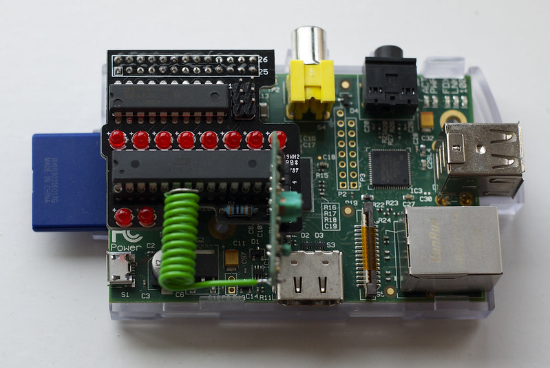
I put the octal latch and LEDs on first, because who doesn’t like a light-show?
Once the almost foolproof part was proved working and I’d warmed up my iron, I
soldered in a socket for the ATmega, the status lights, ICSP pins and a row
of headers for the radio module.
I tested with a full Boarduino transmitting and with picocom receiving
on the Pi-side: it worked!
Repurposing
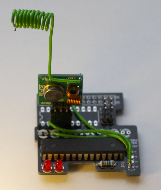
Although this board was designed for the receiver, I only need one of those, and I
have 10 boards. I’ve since repurposed one of the boards for a test transmitter:
(If I was doing this again, I would put unoccupied through-holes on the board,
but this works fine.)
This test transmitter just echos the “hello” string over the radio. Adding
a real analogue input and reworking the design to be lower power is probably
going to justify a new board - but with this I can test how far away I
can get from the transmitter before I get packet loss.
Conclusion
The schematic and Arduino code are available from the GitHub project page.
DirtyPCBs.com is amazing. Chinese surface mail is slow (but cheap). If I can
design a PCB, so can you.


 Previous Topic