This post originated from an RSS feed registered with Python Buzz
by Phillip Pearson.
Original Post: Debugging the ESP8266 with JTAG -- breakout board with an SWD-style JTAG connector
Feed Title: Second p0st
Feed URL: http://www.myelin.co.nz/post/rss.xml
Feed Description: Tech notes and web hackery from the guy that brought you bzero, Python Community Server, the Blogging Ecosystem and the Internet Topic Exchange
This doesn't seem to have attracted nearly as much attention as I would have thought. Maybe because hobbyists nowadays are used to the Arduino platform, which doesn't include any on-chip debugging support? (Unless you cut some traces and plug in an Atmel ICE unit.) The ubiquitous availability of on-chip debugging is probably my favourite thing about working with ARM Cortex-M chips; it's kinda painful to go back to an environment where I don't have access to that. I'm currently working on some DMX512 hardware, and recently had a yak-shaving-like need to implement my own non-blocking software UART; this wouldn't have been possible without being able to breakpoint and single-step using KDS, SWD, my J-Link, and my Saleae Logic 8.
Anyway, I'm super excited to give this a try on an ESP8266. Unfortunately all my ESP-03 modules are soldered into boards that tie GPIO15/MTDO to ground, and otherwise I only have a couple of ESP-01 units, which don't bring out the JTAG pins.
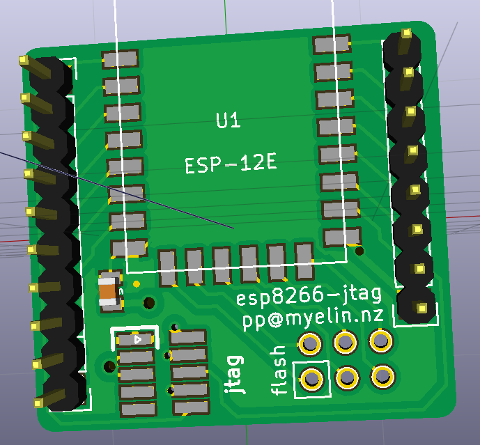
So... time to get an ESP-12 or two, and whip up a board with all the bits and pieces JTAG requires!
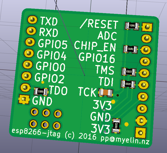
- Pulldown on TDO. This should really be a pullup, except that TDO/GPIO15 is part of the boot_sel combo (GPIO15:GPIO0:GPIO2), which has to be 011 to boot from flash, so GPIO15 must be pulled low if you ever want to boot without an attached debugger.
- Pulldown on TCK. This is also nonstandard; most JTAG diagrams show no pull resistors on TCK, but have it terminated with 68R and 100pF in series to ground. ARM recommends a pulldown, though -- to avoid spurious clock edges during hot-plugging -- so I'm going with that.
- Pullups on TDI and TMS. This is standard JTAG.
- Pullups on CHIP_EN and /RESET -- always required on the ESP8266.
I chose to use an SWD-style 2x5 1.27mm connector, which will hopefully let me connect this to my J-Link using the same cable that I use for ARM debugging. Here's how the board looks: