
Industry pundits have been predicting the direction personal computers (PC) and consumer electronics products (CE) would eventually take. The basic technologies had all been present for some time: Widely accepted digital media formats for the delivery of audio-visual content, wired and wireless networks in the home as a backplane for device connectivity, and broadband Internet connections for high-speed access to Internet-based content. Nevertheless, the anticipated convergence of personal computers and consumer electronics remained out of reach until recently. The missing ingredient: a widely-adopted, standards-based network technology to allow devices from the personal computer and consumer electronics worlds to offer their functionalities and advertise their services to other network devices.
The Arrival of Digital Home Convergence
Since its introduction in 1999, UPnP technology has been steadily gaining industry support as the preferred device discovery and control protocol for IP networks in the home and small office. Today, the UPnP Forum has over 700 member companies from industries as diverse as personal computers, consumer electronics, home automation and control, home security, printing, photography, and computer networking. UPnP Forum working groups have developed standards for several kinds of network devices, such as printers, cameras, scanners, and Internet gateways. Each of those standards provides an abstraction of what services each kind of device provides to the network.As a result of those efforts, standards-based products in the market are beginning to break down barriers between PC and CE devices and are providing new usage models to consumers. For example, digital media adapters (DMAs) are devices that reside in the entertainment center with outputs to the television and audio equipment and a wired or wireless connection to the home network. DMAs allow the user to view content from the PC, typically located in another room such as the den or home office, on the TV and stereo in the entertainment center. Because of the UPnP A/V standards, all of the content in the home will soon be aggregated into a single, virtual content store available to any networked UPnP A/V device.
Work in the UPnP Forum continues, with more devices and innovative usage models on the horizon. Consider digital photography. A user will soon be able to take photographs with a digital camera, bring that camera home and set it on the counter. The camera will wirelessly upload the pictures to a central storage location in the home, making those pictures available for viewing on any device capable of image display. To peruse those photos with friends, a user might sit on a couch and view the pictures on a TV. To edit those pictures, a user could access them from the PC. Personal media center devices will allow people to take their pictures with them to show their friends. There will be fewer hurdles of directly transporting pictures from one device to another - content will be automatically transferred and accessed, and all devices will have access to the same content at any time.
A Digital Home Platform
In addition to entertainment-oriented usages of UPnP technology, companies are developing bridging technology to bring devices located on other networks in the home into the realm of UPnP devices. An example: the powerline network. Garage door openers, lights, and switches will soon be available for discovery and control. UPnP technology is a unifying force: it defines a framework for a common, network-based platform for device collaboration.UPnP implicitly enables the notion of a digital home platform: an abstraction that brings coherence to previously separate islands of connectivity in the home. The digital home platform will span wired and wireless networks, entertainment devices, telephone equipment, home control, and so on, linking the various networks in the home into a single logical network of programmable devices, as shown in Figure 1.
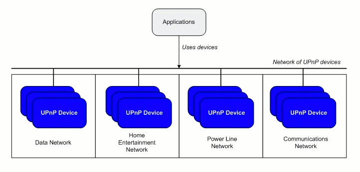
Figure 1 - UPnP: a unifying network technology
Control points on the network, such as the PC in the den, or the television and remote control in the entertainment area, will have programmatic access to all of the devices on the network and will be able to run programs that aggregate the devices into innovative applications.
New Usage Models
Much of the complexity of installing, configuring and using networked devices in the home can be hidden from users by UPnP technology. For example, a person not familiar with networking might bring home a wireless Internet gateway device and, instead of having to learn about IP addresses, packet filtering, ports, and so on, can just plug that device in the power, Ethernet, and phone cables, turn the device on, and that device will just work.In addition, UPnP technology provides an important usability benefit: it helps transform the home computing environment from a simple PC-in-the-den model to a user- or activity-centered model. New usage models are already being developed that support activities in the home in their natural settings. For example, as we've seen with entertainment, content brought in to the PC from the Internet can be enjoyed in the home environment most suitable for music and video - the entertainment center.
In the future, user interface devices will be tailored more closely to user activities, moving beyond the simple keyboard and mouse interface. For example, in the kitchen there might be a durable and easy-to-clean touch screen display that can handle user interaction with a program running on a remote PC. The new UPnP Remote UI is designed to facilitate such a transition. Remote UI enables the separation of application logic from user interface. This will be a boon to new usage models that allow the user to interact with an application from many user interface points throughout the home.
The UPnP Device Architecture
UPnP is built upon existing protocols and formats including HTTP, XML, SOAP, the Document Object Model, and IP multicast. Those elements are used together to define a framework to enable the definition, discovery, and control of network devices.Committees, or working groups, of the UPnP Forum build upon the common framework by collaborating to define standard device types. The UPnP Device Architecture document details the protocols and conventions required of UPnP devices, and explains the basic pattern all UPnP devices follow in their operation:
- Addressing: The device joins the network, acquiring a unique address that entities can use to communicate with the device
- Description: The device summarizes its services and capabilities in a standard format
- Discovery: The device is found by control points that learn about the device's capabilities by retrieving a device description
- Control: The device handles requests from control points
- Eventing: The device notifies registered control points of internal state changes
- Presentation: The device provides an HTML-based administrative interface to allow for direct manipulation and monitoring of the device
Each UPnP phase has related network protocols. The TCP/IP protocol suite and HTTP provide the basic network connectivity for UPnP. Figure 2 shows the basic UPnP protocol stack.
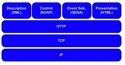
Figure 2 - The UPnP protocol stack
A few aspects of UPnP require the sender to communicate with many recipients. For example, the UPnP device discovery mechanism allows devices to send presence announcements to all of the other devices on the network, letting them know of that device's availability. For that purpose, UPnP relies on a form of HTTP that is sent over multicast UDP, called HTTPMU. In some cases, response messages are sent directly back to the source using HTTP over unicast UDP, called HTTPU. The multicast-oriented protocol stack is shown in Figure 3.
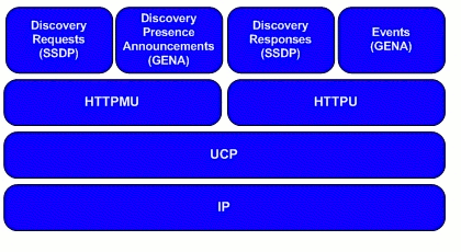
Figure 3 - HTTPMU and HTTPU protocol stack
Devices
A UPnP device can be thought of as a logical container with a unique type. Each UPnP device may offer any number of services, each service with its own unique service type. By itself, a device does nothing more than provide self-describing information such as the manufacturer, model name, and serial number. A device's services provide the real functionality.A UPnP device may also contain other devices. That logical composition of devices gives the designer flexibility when determining how to implement the device. It also allows the embedded device to be discovered and used independently from the main container device. Figure 4 shows a detailed UML class diagram for a UPnP device.
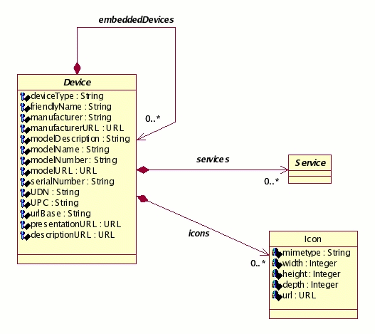
Figure 4 - Class diagram: the UPnP Device
Services
Each service in a UPnP device may contain any number of actions, each action having a set of input parameters and an optional return value. Each action also has a name and an optional set of arguments. Each argument has a name, a value, and a direction. The direction may be either input or output (but not both), depending on whether the argument is passed into the action or is returned from the action to the caller. Each action may also have a return value that provides the result of the action.Those familiar with interface-oriented object model systems, such as Microsoft COM or CORBA, can draw an analogy: a UPnP device is similar to an object, the services are like interfaces supported by the object, and the actions in a service are like functions in an interface.
Each UPnP service also has a service type Uniform Resource Identifier (URI) that uniquely identifies the service. Standard service types are defined by a UPnP Forum working committee. Every service also has a serviceId URI that uniquely identifies the service among all of a device's services. No two services may share the same serviceId. The services that a device must implement are determined by the device's type. The working committees of the UPnP Forum standardize the set of services a device type must support.
Each service may also maintain variables that represent that service's current status. A service may have zero or more such variables. Each state variable has a name, a type, a default value, and a current value. It also has a set of allowed values to describe the range of permissible variable values. Any state variable can trigger events on state changes; when such events occur is determined by a service's implementer.
If a variable triggers an event to indicate a state, that variable is said to be evented. Every input argument to an action is associated with one of the service's state variables, termed the argument's related state variable. One of an action's arguments may be designated as the action's return value. The return value provides the result of the action to the caller. Figure 5 shows a UML class diagram for a UPnP service.
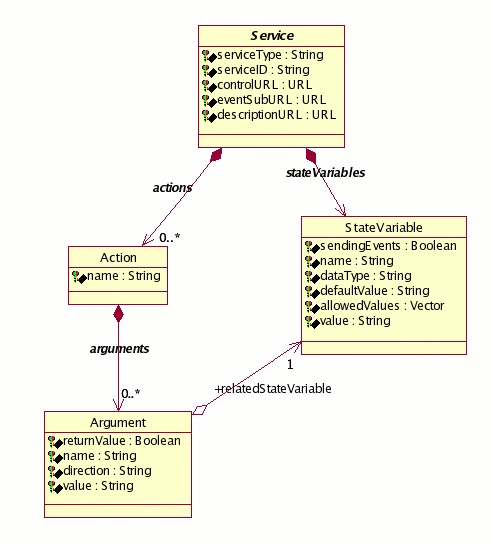
Figure 5 - Class diagram: the UPnP Service
UPnP control points can subscribe to receive indications of state variable changes from a service. When a service detects a change to a state variable, that service notifies any registered control points of that change. For example, a service that renders audio tracks might keep a state variable of the URL of the current track being played. When the track changes, the service sends a state change notification with the new URL to all control points that have registered interest in receiving events from that service.
Control Points
A control point is a network entity that invokes a device's functionality. In client/server computing terms, the control point is the client and the device is the server. Control points invoke actions on services, providing any required input parameters and receiving any output parameters and possibly a return value. Figure 6 shows a control point invoking an action on a UPnP-enabled device that implements a single UPnP device type containing two services.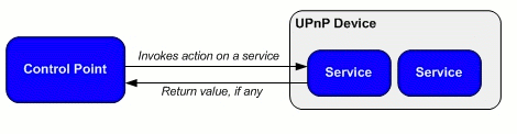
Figure 6 - A control point invoking an action on a service
As the figure illustrates, a control point discovers devices, invokes actions on a device's services, and subscribes to event notifications. A device, on the other hand, responds to invoked actions, sends events when state variables change, and supports a Web page for administrative control (a presentation page in UPnP terminology).
Phases of Operation
Addressing
Addressing is the process by which a device automatically acquires an IP address. It is the first step in the operation of a UPnP device. Addressing allows a device to join the network and to prepare to communicate with other UPnP devices and control points. The addressing protocols built in to UPnP devices allow devices to join an IP network dynamically and to acquire an address without user configuration.Addressing takes into account whether a device is operating in an unmanaged or managed network. An unmanaged, or ad-hoc, network is a network where there are no pre-existing infrastructure devices (or they are currently inoperable), and the network nodes themselves make up the network. A managed, or infrastructure, network allows devices to acquire an IP address from a DHCP server on the network. As a result, UPnP devices must support both the Dynamic Host Configuration Protocol (DHCP) and the dynamic configuration of private link-local addresses (Auto-IP).
A device first attempts to contact a DHCP service to acquire an address. If it fails to locate a DHCP server, the device uses Auto-IP, which enables devices to select addresses without a DHCP server being present to assign that address. The addresses are taken from a set of well-known, non-routable addresses. DHCP is a UDP-based protocol, while Auto-IP uses the Address Resolution Protocol (ARP).
Description
Description allows devices to list the functionality they provide. Descriptions of devices and their services are contained in XML-based description documents. The device description document contains device information such as manufacturer, make, model, and serial number; a list of services provided by the device; and a list of embedded devices. A service description document contains detailed information about a device's service, the actions that service provides, and the service's parameters and return value. The description documents are used by control points in the device discovery process to learn more about a device. Figure 7 illustrates the device and service description hierarchy.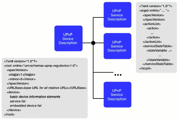
Figure 7 - The UPnP Device and Service Hierarchy
Discovery
Discovery defines how a device announces its presence, and how control points discover it. A UPnP device is like a mini network server that can be discovered and controlled by a UPnP control point. The discovery process enables control points to find devices and services of interest and retrieve information about them. UPnP devices use the Simple Service Discovery Protocol (SSDP) for Discovery. SSDP extends the HTTP (Hypertext Transfer Protocol) header to provide a simple multicast-based discovery protocol.Once a device has acquired an IP address, that device periodically advertises itself and its services on the network. A device includes a URL of its device description XML document in its advertisement and discovery responses. That URL provides control points with the information those control points need to retrieve the device and service descriptions. The description documents are retrieved by control points and parsed to understand all about that device. A vendor can add extensions beyond the basic functions and include those extensions in the description docs. That extension mechanism allows a control point to prefer an optional or vendor-specific interface over the standard one.
Every service contained in a device maintains three URLs that provide the information necessary for control points to communicate with that service:
- The ControlURL is where control points post requests to control the service. A UPnP device vendor specifies one for each device.
- The EventSubURL is where control points post requests to subscribe to events. There is one EventSubURL for each service in a device. If a service has no evented variables, that service does not have eventing. If a service does not have eventing, the EventSubURL element must be present but should be empty.
- The DescriptionURL tells control points the location to retrieve the service description document from. The service description XML document is returned via an HTTP GET request. Sometimes even after recognizing a UPnP Forum device type, a control point discovers individual service description documents. Since some service interfaces are optional, not all vendors may implement a particular capability. For example, a UPnP-enabled printer that does not support color printing will likely choose not to implement actions to adjust color properties.
Figure 8 illustrates the steps taken by a UPnP control point application to discover a device's capabilities.
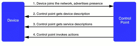
Figure�8 - Retrieving Device and Service DescriptionsControl
Control is the UPnP phase when control points invoke the actions of a device's services. When a service receives a control message, that service acts upon that message. UPnP relies on the Simple Object Access Protocol (SOAP) for device control. SOAP brings together XML and HTTP to provide a Web-based messaging and remote procedure call mechanism. XML expresses the message content, while HTTP sends messages to their destination. SOAP is specified as a set of conventions that govern the format and processing rules of SOAP messages. SOAP consists of four parts:- The SOAP envelope An XML schema that defines a framework for describing what is in a message, how to process it, and whether that processing is optional or mandatory.
- The SOAP encoding rules Another XML schema that defines a set of rules for expressing instances of application-defined data types.
- The SOAP binding A convention for using different transport protocols. SOAP can potentially be used in combination with a variety of other transport protocols (however SOAP messages are most commonly carried by HTTP).
- The SOAP RPC representation A convention for representing remote procedure calls and responses.
The SOAP message is the basic unit of communication between peers. SOAP messages are written in XML, making SOAP platform independent: any system capable of creating and parsing XML documents can send and receive SOAP messages. The power of XML allows SOAP messages to be fairly complex in structure and to transmit highly complex data types.
Eventing
UPnP employs an event notification system using a publisher/subscriber model in which control points may subscribe to events sent by a service, and services publish event notifications to subscribers. An event is a message from a service to subscribed control points. Events keep control points informed of changes in state associated with a service. Control points subscribe to events, and the service notifies interested control points of events.A control point interested in receiving notification of state variable changes subscribes to an event source by sending a subscription request that includes:
- The service of interest
- A URL to which the events can be sent
- A subscription time for the event notification
A subscription is a request to receive all state variable changes: UPnP provides no mechanism to subscribe to events on a variable-by-variable basis. If a service accepts the subscription request, that service responds with a unique subscription identifier and the duration for the subscription. The unique identifier allows the control point to refer to the subscription in subsequent requests to the service, such as renewing or canceling the subscription. The duration specifies the length of time that the subscription is valid and maintained by the service. If one or more of a service's state variables are evented, the service publishes updates to the subscribers when the variables change.
Figure 9 shows how a control point communicates with a service to subscribe to and receive notifications of state variable changes.
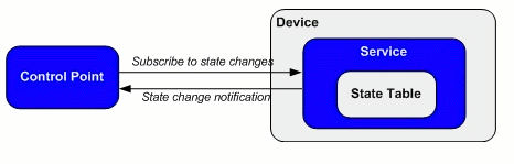
Figure 9 - State Changes and NotificationsAll subscribers are sent all event messages. Subscribers receive event messages for all evented variables, and event messages are sent regardless of the reason the state variable changed, e.g., in response to an action request or due to an internal state change. UPnP's only guarantees that a message gets delivered to a subscriber is that it the eventing protocol (GENA) uses TCP for transport.
When a subscription expires, the subscription identifier becomes invalid, and the publisher stops sending event messages to that subscriber. If the subscriber tries to send any message other than a subscription request message - a subscription renewal request or a subscription cancellation message - the publisher rejects that message due to the invalid subscription identifier.
All subscriptions must be renewed periodically for the control points to continue to receive notifications. To keep a subscription active, a control point must send a renewal message before that subscription expires. The renewal message is sent to the same URL as the original subscription message, but the renewal message does not include a delivery URL for event messages. Instead, the renewal message includes the subscription identifier received in the initial message accepting the subscription. When a control point no longer wants to receive events from a service, the control point can cancel its subscription.
Presentation
Presentation is the process where a device presents a browser-based user interface for manual user control and to allow viewing of that device's status. Each UPnP device contains an internal HTTP Web server and may provide a Web page for browser-based clients. That Web page serves as the device's manual interface that complements the device's programmatic SOAP-based control interface. The browser-based interface is used to control the device, to change operational parameters, to view device and service information, or for any other device-specific functionality implemented by the manufacturer. The presentation page provides a simple, consistent way to work with UPnP devices and requires no custom software.Superset Standards: NMPR, DLNA
UPnP is the foundation of other home networking standards such as the Digital Living Network Alliance (formerly the Digital Home Working Group) and Intel's Networked Media Products Requirements (NMPR) specifications. These upcoming specifications add to the UPnP foundation, going beyond the basic UPnP device architecture specification to include media formats and other issues such as Digital Rights Management (DRM) to ensure a higher degree of device interoperability.UPnP also addresses many of the new usage models of the digital home mentioned earlier. The UPnP Remote User Interface (RUI) is a new standard recently released by the UPnP Forum. Remote UI allows for the splitting of core application logic from user interaction, with each implemented on different devices. Essentially, Remote UI moves the point of user interaction away from an application running on a specific device, such as a PC or a CE (Consumer Electronic) device, to one or more Remote UI devices. The RemoteUIClientDevice supplies input and output services such as mouse, keyboard, and display that together comprise the user interface. Applications run on a host supporting the RemoteUIServerDevice and are matched with compatible Remote UI devices.
The new Remote UI standard will enable vendors to create devices that free the user from the location of the application. For example, a user could use an e-Book style device supporting the RemoteUIClient standard to read the evening news in a comfortable chair in the family room while the application building the user's custom newspaper is running on the desktop PC in the den and pulling in content from the Internet.
Summary
The UPnP Device Architecture provides a common framework upon which interoperable devices and services can be built, while still allowing vendors the freedom to innovate and create interesting new device types for the digital home. UPnP technology is the foundation for higher levels of automation and new usage models in the home and office.Resources:
Universal Plug and Play
http://www.upnp.orgDigital Living Network Alliance
http://www.dlna.orgNetworked Media Product Requirements (NMPR)
http://www.intel.com/technology/dhdevnetSOAP, XML, HTTP, and other Web Standards
http://www.w3c.orgUPnP Design by Example
http://www.amazon.comMark Walker, Jim Edwards, Michael Jeronimo, John G. Ritchie, Ylian Saint-Hilaire, Remote I/O: Freeing the Experience from the Platform with UPnP Architecture. in Intel Technology Journal, Vol. 6, Issue 4 (2002).
- The SOAP envelope An XML schema that defines a framework for describing what is in a message, how to process it, and whether that processing is optional or mandatory.
Talk back!
Have an opinion? Readers have already posted 2 comments about this article. Why not add yours?
About the author
-
Artima provides consulting and training services to help you make the most of Scala, reactive
and functional programming, enterprise systems, big data, and testing.
2070 N Broadway Unit 305
Walnut Creek CA 94597
USA
(925) 918-1769 (Phone)